Designing Parts for Injection Molding
Before a mold is designed to produce an injection molded part, there are various design concepts to consider for a part to be molded properly and efficiently. This section will discuss some of these design considerations and their purposes, empowering you to design parts that require fewer iterations.
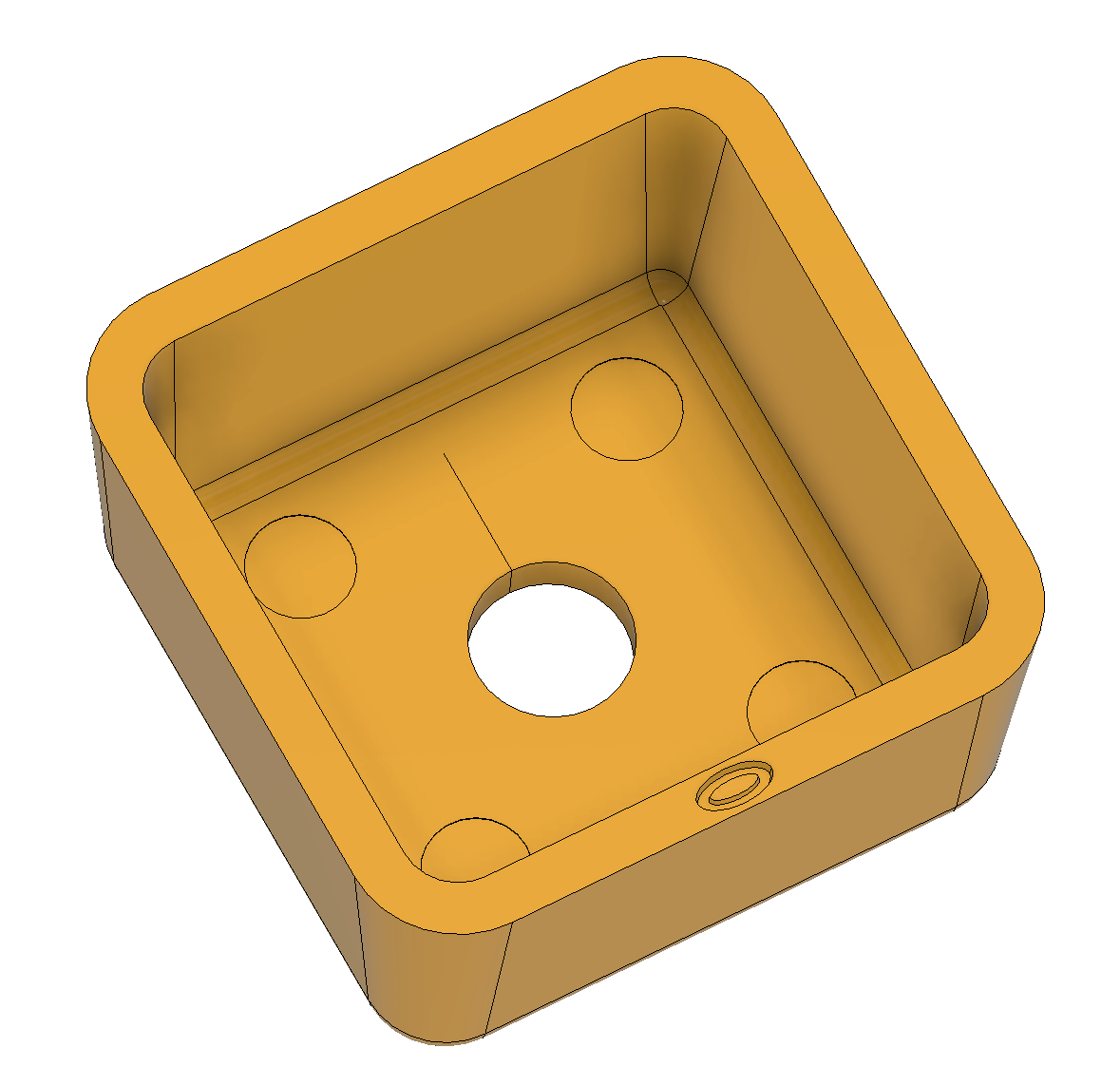
Wall Thickness
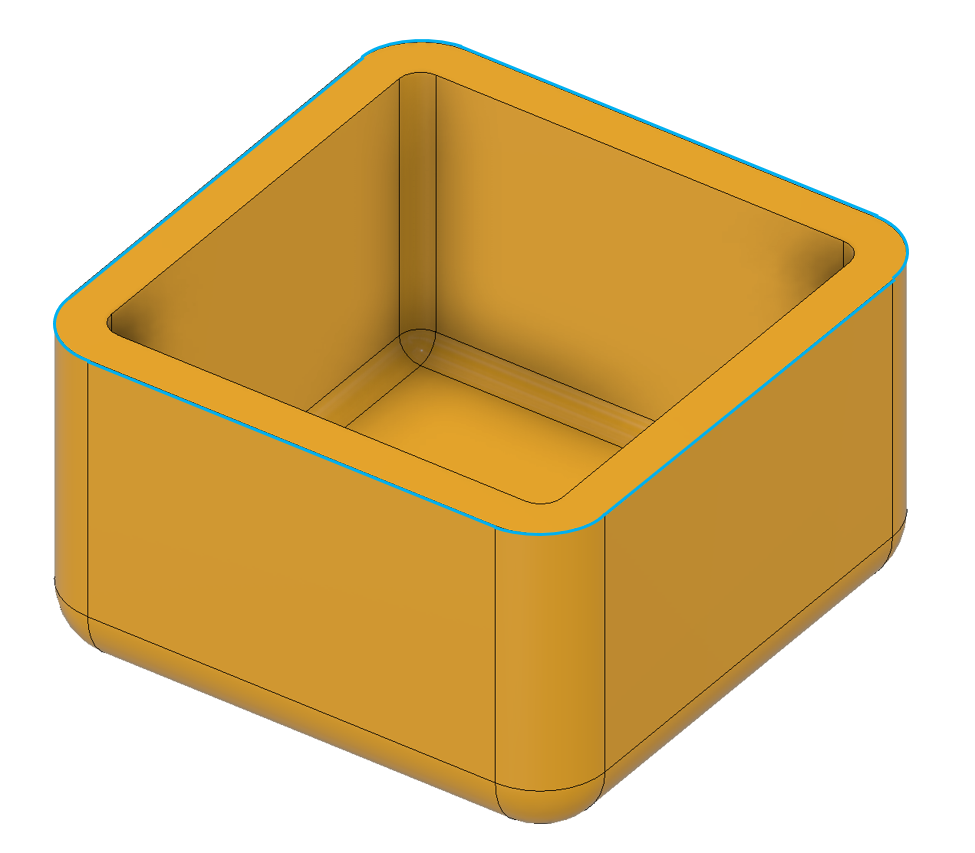
When designing a part for injection molding, wall thickness is often the first thing we will consider. The wall thickness must allow the part to hit strength or flexibility requirements while allowing the part to fill in the mold at a reasonable pressure for a given material. Our technical staff endeavour to design parts with constant wall thicknesses and smooth transitions to avoid unexpected warpage. This can be achieved by:
- shelling or cutting away thick spots
- adding ribs at roughly half wall thickness to maintain strength
- adding fillets, or rounding inner and outer corners
These features simplify and increase the lifespan of mold tooling while providing a smoother flow path for the molten plastic, thereby reducing upfront costs and improving part performance.
Parting Line
This concept may seem trivial; because the part inside the mold must be removed every cycle, the mold must split. The line where the surfaces of the mold halves (often referred to as the A-side for the cosmetic or cavity side, and B-side for the non-cosmetic or core side) split is called the parting line. The more complicated the parting line, the greater the cost and turnaround time of tooling.
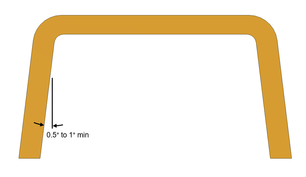
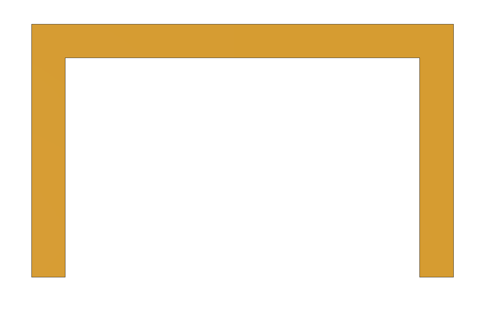
Draft
Draft on plastic parts refers to taper or angle on the wall of the part that would otherwise be perpendicular to the mold parting surface. We generally recommend a minimum of 0.5 to 1 degrees of draft per side, with more draft often being preferred. It is worth noting that more draft will be necessary to allow the part to be molded if texture is desired on a part surface.
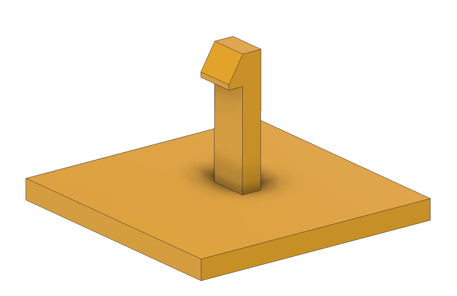
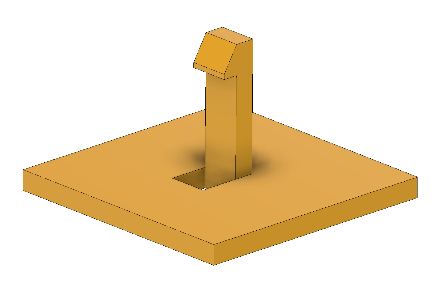
Undercuts
An undercut is a feature in a plastic part that would prevent the part from being removed from the mold. A common example of undercuts would be a snap feature. If the snap feature is at the end of an arm in the middle of the part, it would be trapped in the mold. If the snap feature is moved to the edge of the part, or the floor underneath the snap is opened up with a hole, the snap can be created with a jump in the parting line. In some instances, moving or changing an undercut feature is not an option. Undercuts can be formed in the mold by a variety of mold action components:
- lifters
- core-pulls or sliders
- spinning cores
- collapsing cores
Adding these items to a mold can create very complex shapes that would otherwise be impossible to mold, but they increase mold tooling costs drastically, depending on the complexity of the feature. For more information about undercuts and mold action, fill out our contact form to get in touch with our technical staff.
Gates and Ejectors
One of the last things that many designers will consider is how to gate and eject the part. There are various types of gates that all have cost trade-offs, but the important thing to understand is how plastic will get from outside of the mold into the part. As a part designer, it is important to consider the following:
- How will the part be gated i.e., how will plastic enter the part?
- Will the gate work with the planned parting line?
- Will the gate leave a noticeable mark in a poor location?
- Is a recess required for the gate if some plastic is left behind by trimming?
- Will weld lines caused by the gate location with respect to holes in the part create a point of failure in the part?
- Which faces of the part are cosmetic and which faces can have ejector marks on them?
- As the plastic shrinks, will it grip onto the correct side of the mold to facilitate ejection?
A lot of broad concepts were melted down into the above lists. For more information about gate types and ejector systems, or any other questions about designing for injection molding, fill out our contact form to get in touch with our technical staff.